Can rotary encoders from HEIDENHAIN process other temperature sensor types (e.g., the PT 1000) besides the KTY 84-130?
Rotary encoders from HEIDENHAIN are currently designed for the connection of KTY 84-130 temperature sensors. Future generations will be capable of processing other temperature sensor types (e.g., the PT 1000) in addition to the KTY 84-130.
However, the subsequent electronics or the rotary encoder installed in the motor can already now be configured to automatically detect the connected temperature sensor type. Information on the adaptations to the EnDat specification and recommendations for manufacturers of motors or subsequent electronics can be found in the EnDat Application Notes in the chapter “Processing of various temperature sensor types.” For more information on the compensation calculation by the subsequent electronics, please refer to the “Encoders for Servo Drives” brochure in the chapter “Temperature measurement in motors.”
EnDat multi-channel master
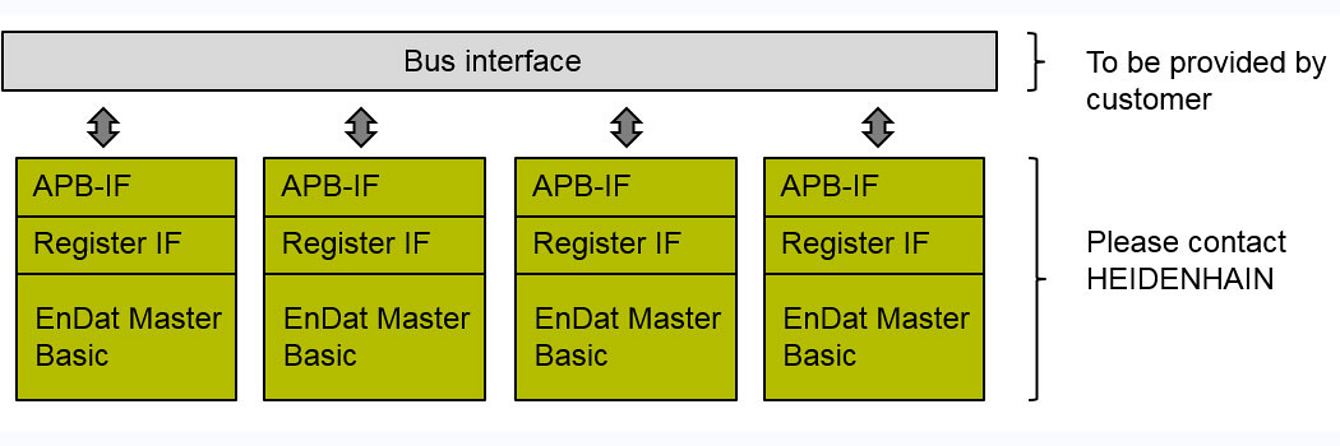
Multi-channel master: Use of the EnDat Master Basic
- EnDat Master Basic is supplied as EDIF netlist (encrypted VHDL code available on request)
- Register interface and APB interface are included
- To be provided by customer:
- Bus interface
Advantages
- Low cost of design and testing Bus interface: e.g. APB to SPI is commercially available
Disadvantages
- The number of logic elements (LE) is usually higher in comparison to a solution with EnDat Master Reduced
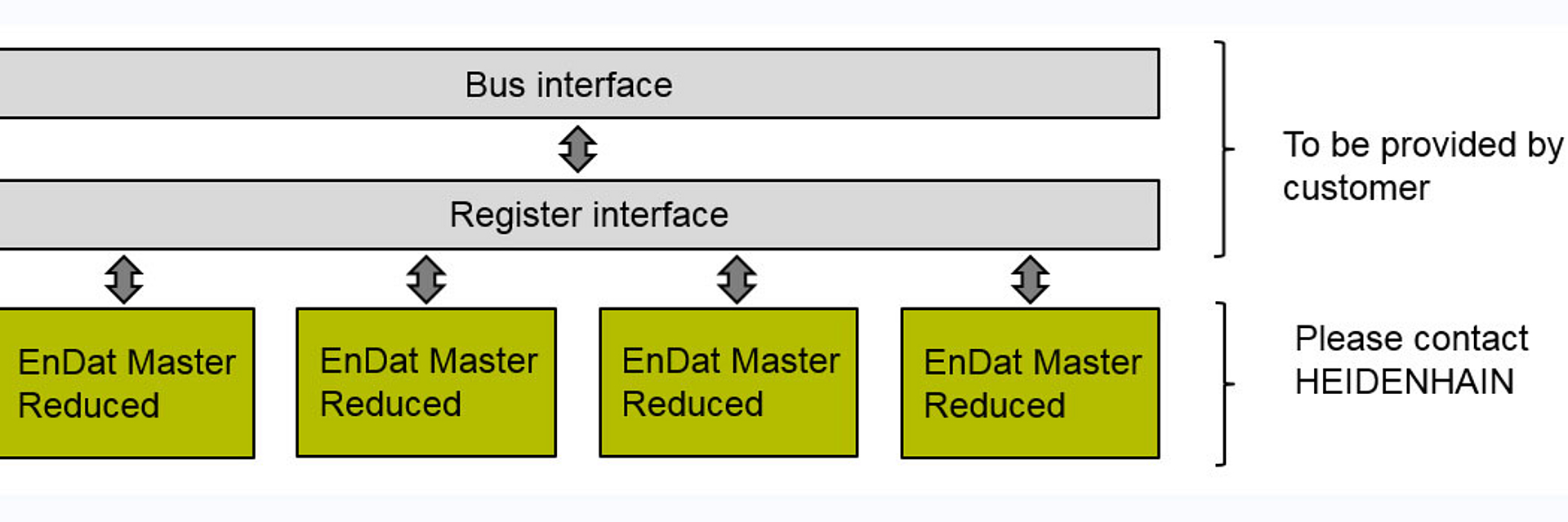
Multi-channel master: Use of the EnDat Master Reduced
- EnDat Master Reduced is supplied as VHDL code
- To be provided by customer:
- Register interface
- Bus interface
Benefits
- The solution usually has fewer logic elements (LE) than does a solution with the EnDat Master Basic
- The register interface can be tailored to the customer's needs
Disadvantage
- Higher cost of design and testing
Are HEIDENHAIN encoders designed for the cyclic storage of data?
RS-485 transceiver: What requirements or recommendations are there?
The following RS-485 transceivers with fail-safe receivers are currently recommended by HEIDENHAIN, depending on the transmission frequency, temperature and supply voltage requirements. Identical blocks (same internal signal propagation time) must be used for clock and data:
- THVD1450 (recommended for the common implementation of EnDat 2.2 and EnDat 3)
- SN65HVD78
- MAX14841
- SN75HVD1176
These are the essential requirements on the RS-485 transceiver:
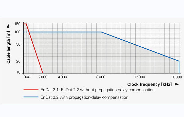
- For EnDat2.2, HEIDENHAIN recommends RS-485 transceivers with a data rate of at least 32 Mbps. This makes it possible to support the maximum clock frequency of 16 MHz defined for EnDat 2.2.
- For EnDat2.1, HEIDENHAIN recommends RS-485 transceivers with a data rate of at least 4 Mbps. This makes it possible to support the maximum clock frequency of 2 MHz defined for EnDat 2.1.
- The edge steepness of the driver (rise or fall time) must be <25 ns (for EnDat 2.1 and EnDat 2.2).
Application test under operating conditions:
In all cases, an application test must be conducted, taking into account the complete transmission distance (RS-485 transceiver, cable, connector, etc.). This also applies to the application-specific requirements for the operating conditions, including voltage supply, temperature, EMC and ESD.
Do I have to set the MRS code again after a reset command?
General information on the processing of error messages, warnings and error handling in the interface:
See also the “Sequences and data structures” chapter of the EnDat Application Note.
Error messages:
The two composite error bits F1 and F2 should be monitored in every query. F1 and F2 are generated independently of each other, and must be evaluated separately from each other. It is recommended that errors and warnings be buffered in the subsequent electronics before they are cleared (for diagnostic purposes at a later date, e.g. error log). Clearing of errors and warnings is basically possible with EnDat 2.1 and EnDat 2.2 commands. However, not all causes of errors can be reset within one communication cycle with the EnDat 2.2 command. In these cases the error messages can remain set. The following priorities for the clearing of errors are the result (the timing requirements of an application decide when the next priority stage is to be switched to):
- Stage 1: Clearing with EnDat 2.2 mode commands in the control cycle
Resetting of error causes that can be reset within one control cycle - Stage 2: Clearing with EnDat 2.1 mode commands
Resetting of error causes that require the encoder to be re-initialized - Stage 3: Switching the unit off and on again
Resetting of error causes that require the encoder to be entirely restarted
Warnings:
The group bit for warnings is transmitted with the additional data. The warning bit should be queried at regular intervals, even if the application does not require the processing of additional data.
Error handling of the interface:
Along with the CRC check there are three different types of errors, which should also be monitored continuously; see Attachment A2 of the EnDat specification.
Also see the “EnDat Monitoring Functions” section of the EnDat Application Note.
Notes:
- Errors and warnings should be reset independently of each other; see the sequence “Clearing errors or warnings”.
- As long as the encoder outputs a group error bit, it must be assumed that the values transmitted by the encoder, particularly the position values, are erroneous.
- With incremental encoders certain error states can only be detected after traversing the reference mark(s).
What is the best way to start the implementation of EnDat?
- See the “How to get started” chapter in the EnDat Application Note
- See the “Implementation” section on the website
What is the simplest method for setting up EnDat communication with an encoder?
Which status messages does an EnDat transmission have, or which status messages should be checked?
When must the change in data direction occur?
| 1st clock period: | The driver in the encoder is deactivated |
| 2nd clock period: | The driver in the subsequent electronics is activated |
| 3rd to 8th clock period: | Transmission of the mode word |
| 9th clock period: | The driver in the subsequent electronics is deactivated |
| 10th clock period: | The driver in the encoder is activated |
Is it necessary to transmit the correct number of clock pulses to the encoder?
Yes
- Before the first position-value request, word 13 of the EnDat 2.1 parameters must be read out, so that the subsequent electronics can correctly determine the number of clock pulses to be sent. EnDat 2.1 commands must be used to read out the information.
- If not enough clock pulses are transmitted, then some information will not be available to the user, and the encoder hangs in the middle of the communication cycle. So under certain circumstances, the next communication will fail.
- If too many clock pulses are transmitted, then the encoder interprets this as a continuous clock. The encoder is then within a communication cycle again, and under circumstances the next communication will fail.
- The communication with the encoder may seem to be functioning, but if the timing changes slightly, for example, it will fail suddenly. Sporadic communication errors can also occur.
How do I correctly program the OEM memory range?
- In principle the memory is freely programmable. HEIDENHAIN does not have requirements for the contents of the programming.
- The memory is divided into four areas. These areas can be used either by the OEM (parameters of the OEM areas 1..4) or by the encoder manufacturer for compensation values (compensation values areas 1..4).
- The content of the compensation-value areas is not of interest to the user.
- The EnDat 2.1 parameters (words 9-12, interrogation of words 9 and 10 suffices) contain information on whether the OEM area is supported, and which addresses within an available area can be addressed.
- Different families of encoders support different OEM memory areas and different address areas. Therefore, the assignment of the OEM areas must be read out for each and every encoder.
- For this reason, the subsequent electronics should form addresses relative to the determined values, and not use absolute addresses. The programming must be adapted to the individual encoder.
(See also the EnDat Application Note, Chapter "OEM Memory Area".)
Error messages are set after power-on. Why?
- After the encoder has been powered, error messages can be set. Also refer to the EnDat specification.
- Please refer to the "Procedure After Switch-On" section in Chapter 2 of the EnDat Application Note.
- Certain types of measuring devices, such as those with buffer battery backup or incremental encoders, require particular measures after switch-on; see also the corresponding chapter of the EnDat Application Note.
Other information regarding errors and warnings:
- The error word can be reset; individual error bits cannot be reset (see specification).
- Not every encoder supports all alarms. The alarms that are supported can be read out from the encoder. Alarms that are not supported should be masked out.
- This way the control can determine whether the errors "demanded" by the application are even supported.
- In the future, additional error messages may be used by HEIDENHAIN !
Can write-protection be rescinded once it is set?
Which order designations are there for EnDat and why?
See also EnDat Technical Information
Interface | Version | Clock frequency | Ordering designation |
EnDat 2.1 | with incremental signals | ≤ 2MHz | EnDat 01 |
EnDat 2.1 | without incremental signals | ≤ 2MHz | EnDat 21 |
EnDat 2.2 | with incremental signals | ≤ 2MHz | EnDat 02 |
EnDat 2.2 | without incremental signals | ≤ 8MHz (bzw. 16 MHz) | EnDat 22 |
bold: Standard version
- Distinguishing features between EnDat 2.1 and 2.2:
- Supply voltage and clock frequency; not command set!
- The ordering designation is indicated on the ID label.
- In the future, EnDat 2.1 encoders (EnDat 01 or 21) will also be available with the EnDat 2.2 command set!
- The clock frequency is based on the properties of the encoder (especially for pluggable cable assemblies and EnDat 02)
- Service encoders: Caution with parameters !
What must be paid attention to if the clock for the encoder must be interrupted during communication, e.g. due to an interrupt?
- If the clock must be interrupted during communication, the clock level must be kept at low. The encoder would interpret a high level for > 10 µs (or > 1.25 µs with reduced recovery time) as the end of the recovery time I, and therefore as the end of the communication cycle.
- With the exception of the LC (max. 30 µs), the clock level can be held at low for several ms.
What must be taken into account for the shortened recovery time?
The EnDat interface provides the possibility to reduce the recovery time for EnDat 2.2 mode commands (see EnDat specification). The reduction of the recovery time makes the realization of very short cycle times possible. The reduced recovery time led to misunderstandings regarding the specification data:
- The reduction of the recovery time is only allowed for EnDat 2.2 mode commands. EnDat 2.1 commands must always be sent with the standard recovery time of 10 .. 30 µs.
- The reduced recovery time must only be set once, because the setting is stored in the EEPROM.
- If the reduction of the recovery time is set by the customer (see EnDat specification), then only mode commands (2.1 or 2.2) with high frequency may be sent after the first EnDat 2.2 mode command with high frequency (> 1 MHz) has been sent. Switching back to the slow frequency (< 1 MHz) and EnDat 2.1 mode commands can cause problems with certain encoders because this operating mode is not available
- If it is necessary to switch from high frequency (> 1 MHz) to low frequency, the following sequence should be followed:
1) Deactivation of all selected additional information
2) Transmission of an EnDat 2.1 command with high transmission frequency
3) Switchover to low transmission frequency
Recommendations:
- The shortened recovery time should only be used if this is necessary for reducing the cycle times.
- If the reduced recovery time is used, only EnDat 2.2 mode commands should be used in closed-loop control operation.
- Avoid switching from high to low transmission frequencies.
Parameters of the encoder manufacturer
Do I have to poll the start bit during a position request?
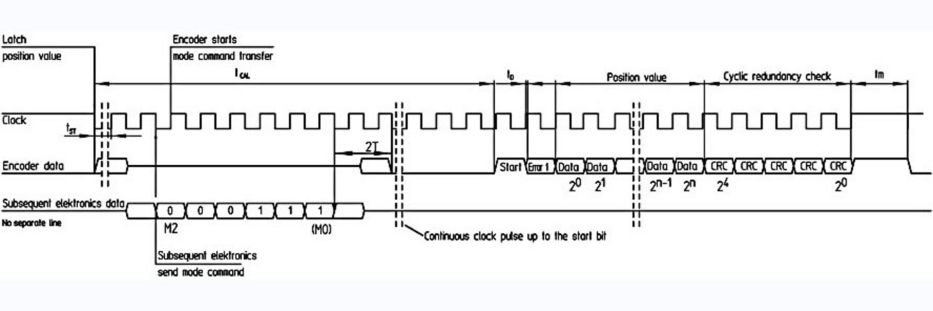
In the diagram in the EnDat specification it appears as if, after sending the mode word, I have to keep the clock at LOW, wait at least the time tCAL, and then the start bit appears immediately with the first clock pulse. I tried that with an encoder, and it worked. Is this correct, or do I continually have to send clock pulses and poll the start bit? A waiting period of 1 ms must be maintained when switching.
Answer:
Unfortunately this is an incorrect interpretation of the diagram. It cannot be guaranteed that the behavior you described applies to all different encoder models. The dashed lines in the diagram indicate that the clock must continue to be sent to the encoder. The start bit must be polled; i.e. clock pulses must be sent until the start bit is sent. That is what the dashed lines in the diagram indicate. The EnDat 2.1 specifications and the EnDat 2.2 specifications refer to Appendix A4 and Appendix A5, respectively, several times. The timing for the EnDat 2.1 position command is described in Appendix A4/A5. Continued clocking while polling the start bit is described there. The time tCAL indicates the earliest possible time at which the position value can be retrieved from the encoder. The start bit must be polled independently of tCAL.
What needs to be considered during booting of the encoder?
Caption
(1) | Build-up time of supply voltage until Up.min is reached should be > 10 V/sec. |
(2) | The 1 Vpp incremental signals attain valid values after at most 1.3 sec. |
(3) | The encoder can be recognized as an EnDat or SSI encoder by the logic level on the data line, after power has been switched on. |
(4) | Clock pulse edges during t1 or t2 can interrupt booting; this can only be corrected by switching the encoder off and then on again. |
(5) | A first EnDat request (falling edge) is permissible once t3 has ended after at least 1 ms (there is no maximum time limit). After the first clock pulse, the direction of data on the data line is reversed (this is why the data line is then at “high impedance”). |
(6) | The encoder requires a defined reset: Falling edge + end of recovery time; For the duration of the low phase the following applies: 0.125 < tlow < 30 µs |
(7) | t1: Boot or reset time of the EnDat encoder t2: Initialization phase of the EnDat encoder t3: Must be maintained for downward compatibility to EnDat 2.1 |
Which encoder profiles or encoder types does EnDat support?
What must be considered with incremental encoders with EnDat interface?
Which types of additional data are supported by an encoder, and which error reactions must be noted?
See the EnDat Application Note, Chapter 2:
“The additional data is saved in the non-volatile memory of the encoder, and not in the EEPROM. This is necessary to be able to switch between the pieces of additional data within a control cycle. Each additional data was assigned its own MRC code so that only one mode command is necessary for switchover. An address must not be specified. Not all encoders provide the full range of additional data. The available additional data can be read out of the EnDat 2.2 parameter, words 0 and 1.”/p>
As a rule, only supported additional data should be selected. If additional data that is not supported is selected, EnDat error type III is issued (see the EnDat Specification). In rare exceptions, a CRC error can be issued instead during the transmission of the corresponding additional data.
Can the operating status error sources and the error or warning register be read at the same time?
Error bits F1 and F2 play a central role here; see also the EnDat Application Note, Chapter 2, in the section on “General information on the processing of error messages, warnings and error handling in the interface.” This means that an error reaction should be triggered in reference to F1 or F2. Information contained in the error or warning register or in the operating status error sources is complementary information. For more information, see the EnDat Application Note, Chapter 7.
Simultaneous reading of the error or warning register through additional data 1 and of the operating status error sources through additional data 2 is not defined for the EnDat 2.2 interface, and can result in incorrect information.
What must be considered for encoders with a battery-buffered revolution counter?
Which data width should be made available to EnDat encoders? Are 32 bits enough?
EnDat 2.1 | Maximum 40-bit data width for the position value. |
EnDat 2.2 | Maximum 48-bit data width for the position value. |
In general | It is recommended that the maximum possible data widths be available, so that future generations of encoders can also be connected. The trend is towards ever higher resolutions. |
32-bit data width | Definitively not enough. For example, the EQN 1337 has 12-bit multiturn and 25-bit singleturn resolution, for a total of 37 bits of position information. |


